


Use Vertical “Stacking” for Dust Control
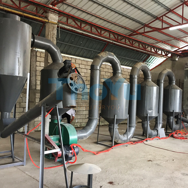
Place cyclone/bag filter closer to the wall and use a compact platform. Saving 6–10 m² is common versus scattered placements, while improving duct straightness.

In many biomass and wood-processing plants, the real bottleneck is not drying capacity—it is floor area, maintenance access, and how quickly an installation can be commissioned without disrupting upstream production. This guide explains a practical, field-tested installation workflow for a compact wood shavings rotary drum dryer, with a strong focus on space-efficient layout, foundation requirements, commissioning steps, and common mistakes that cause rework.
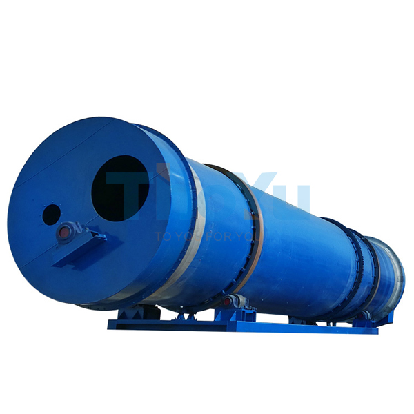
A compact drum dryer configuration is not just a shorter cylinder; it is a system-level design that reduces the footprint of the hot-air path, shortens ducting, and consolidates dust collection and discharge routing. For wood shavings, a commonly deployed compact line targets stable moisture reduction (for example, 45–55% down to 10–15%, depending on fuel and process settings).
| Item | Typical Range (Compact Line) | Why It Matters for Space |
|---|---|---|
| Drum diameter × length | 1.2–2.2 m × 6–12 m | Defines main equipment envelope and maintenance corridor |
| Footprint (complete line) | ~55–120 m² | Determines whether a single-bay workshop can host the system |
| Clear height requirement | 4.5–7 m (incl. ducting) | Affects cyclones, elbows, and inspection access |
| Installed power (system) | 30–110 kW | Impacts cable routing, MCC placement, and cable tray congestion |
| Airflow & dust control | Baghouse or cyclone + bag filter | Dictates where you can “stack vertically” to save floor space |
Note: Real values depend on feed moisture, target moisture, heat source, ambient conditions, and local dust emission requirements.
Compact installations succeed when the layout is validated before a single anchor bolt is poured. A fast, reliable method is to confirm these measurements on-site and lock them into a single drawing package.
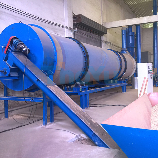
A rotary drum dryer operates with continuous rotation, thermal expansion, and vibration loads. A compact line can still impose significant dynamic stress on foundations—especially at the support rollers, drive assembly, and induced draft fan base.
Best practice: cast-in reference points (centerlines) and keep them visible after floor finishing. It speeds alignment and shortens downtime during service.
The workflow below is designed to reduce lifting conflicts, shorten alignment time, and keep the hot-air circuit compact—key for workshops where every meter matters.
Many factories over-focus on squeezing the footprint, then discover they cannot replace bearings, open inspection doors, or remove filter bags without dismantling ducting. A compact wood shavings drum dryer should be dense, not cramped.
Place cyclone/bag filter closer to the wall and use a compact platform. Saving 6–10 m² is common versus scattered placements, while improving duct straightness.
Reserve 800–1000 mm minimum on the drive side and at least 600–800 mm at inspection doors. This prevents “maintenance by dismantling.”
Each sharp elbow adds pressure loss, raising fan load. A cleaner route often reduces system power demand by 5–12% in real operation.
Avoid crossing paths between raw shavings and dried product. Clean routing reduces dust spread and shortens operator travel time.
In a typical mid-sized woodworking plant, a narrow workshop bay can still host a compact drying line if the system is arranged around the drum axis and the dust-control unit is consolidated. One practical approach is to align the drum parallel to the longest wall, locate the hot-air source at the end (for clear safety zoning), and route discharge toward packaging to avoid backtracking.
| Adjustment | Typical Result | Operational Benefit |
|---|---|---|
| Place filter & fan as one “service block” | Saves ~8 m² floor area | Faster filter access; less duct leakage risk |
| Reduce duct elbows by redesigning exhaust route | Cuts fan load ~5–12% | Lower energy consumption; steadier negative pressure |
| Standardize platforms & ladders | Shortens install time 1–3 days | Safer inspection; consistent operator routine |
For a compact line with prepared foundations, a typical range is 10–20 working days from equipment positioning to wet commissioning, depending on lifting conditions, local fabrication, and electrical scope.
Many projects become feasible when the bay can provide a straight length for the drum plus service corridor. As a practical reference, plan for a usable bay of roughly 14–22 m in length and 5–8 m in width for a compact configuration—then validate with a layout drawing.
The biggest gains usually come from reduced duct losses, steadier negative pressure control, and better heat utilization. Plants commonly report 5–15% lower electricity use on the fan side after optimizing duct routing and sealing.
For downstream uses like pellets or briquettes, many operations target 10–15% final moisture. The stable target depends on incoming variability, particle size distribution, and the thermal profile used during commissioning.
A compact installation is most successful when the supplier provides a drawing package that matches your workshop constraints, maintenance routines, and dust-control standards. For engineering teams, the fastest path is to review a footprint layout and utility list before civil work begins—then commission with a predictable ramp-up plan.
Send your workshop dimensions, target moisture, and hourly capacity. A tailored layout can help reduce rework, shorten installation time, and keep maintenance access practical from day one.
Get a Compact Wood Shavings Rotary Drum Dryer Layout & Technical Checklist


